
We recommend deploying TX and RX in an “inchworm method” for optimizing the data management process. This means moving both the TX and RX, rather than “leapfrogging” by moving only one of the devices to the next manhole (see Figure 5).
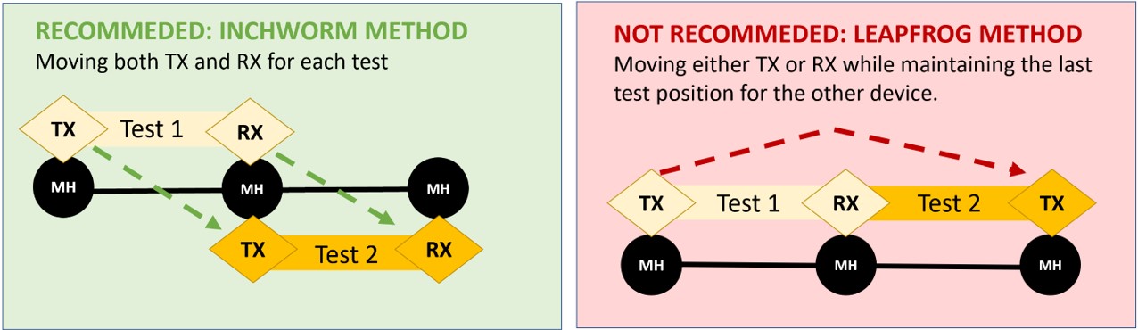
Figure 5. When conducting acoustic tests, we recommend using inchworm method of deploying TX and RX rather than leapfrog method to make it easier to manage and edit the data after downloading.
Steps for Using the SL-RAT® – Based on ASTM Standard Verification Process
Below is an overview of the steps. Please continue reading to see detailed instructions regarding each step.
Step 1. Turn on TX and RX Devices
Turn on both the Transmitter (TX) and the Receiver (RX) by using the toggle switch on the bottom left side of the control boxes. Sync devices and acquire GPS coordinates. Verify operation by going to the menu and selecting “verify operation”. See General Operations.
Step 2. Deploy devices
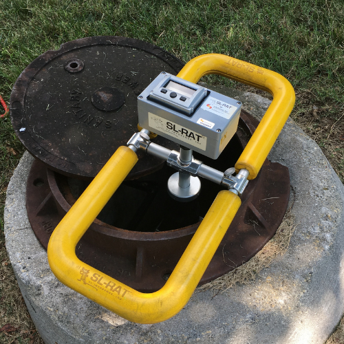
Deploy TX and RX by placing the devices on adjacent manholes (Figure 6). Do not knowingly skip manholes
Step 3. Prepare RX unit for pipe inspection (do not start test yet)
Press “Start Test” on the RX Unit to begin test initialization.
Step 4. Start TX unit, then Start RX Unit
Press “Start Test” on TX device. Then press “Start Test” on RX device. Remember: Start the TX before you start the RX. “Yell” before you “Listen”
Step 5. View Test Results
Test results will be displayed on the RX once the test is complete. The TX should automatically stop producing tones once RX displays score. If it does not, operator can manually stop test by pressing and holding down center button.
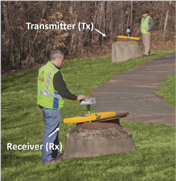
Figure 6. SL-RAT deployment for acoustic measurement of the pipe segment between two adjacent manholes.
Once started, the test is automated. The SL-RAT RX displays real time graphics indicating both the test’s progress and the performance. The SL-RAT TX displays real time graphics indicating the number of tone sequences completed. The SL-RAT RX and TX control and operation are performed through a series of screens on the User Display and through the 3-Button Control.
STEP 1. Turn on both TX and RX Devices
The SL-RAT TX and RX components are provided as a pair. They are factory calibrated to operate as a single device when performing an acoustic measurement.
The TX and RX automatically go through a series of initializing screens on the user display when both devices are turned on (toggle switch is turned to the “on” position) and positioned close to each other (less than 50 feet). They will synchronize data and acquire GPS. It is best practice to turn devices on outside, with a clear view of the sky, so GPS coordinates can be easily acquired (Figure 7).
Once initializing is complete, operators see respective start up screens in Step 2 (RX) and Step 3 (TX).
Verify Operation should be done once a day at the start of the day. Select menu (see General Operations or reference ASTM Standard for details).
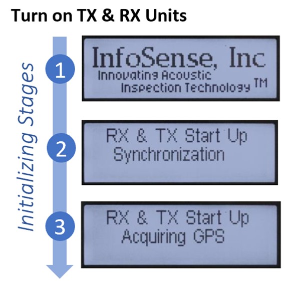
Figure 7. Devices will automatically go through the initializing stages of synchronizing and acquiring GPS when turned on.
* TROUBLESHOOTING – GPS Reset/Cold Start
If a device cannot acquire GPS within three minutes, the operator is given the option of resetting the GPS, by pressing the < Cold Start > button. Operator must verify that they wish to reset the GPS.
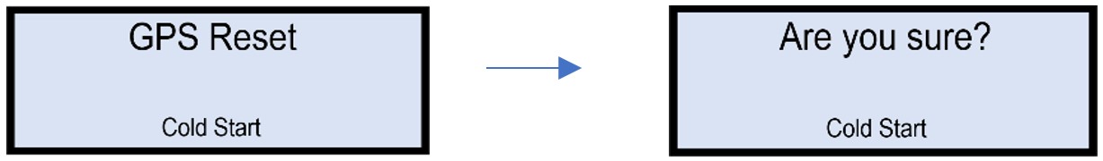
Please note, resetting the GPS takes 15-30 minutes. The device will continue to search for GPS when the “GPS Reset” screen populates, so operator can choose to wait for device to acquire GPS without cold starting, if desired.
STEP 2. Deploy TX and RX units over Adjacent Manholes
An acoustic measurement is typically conducted by deploying the TX and RX components in adjacent manholes. The following guidelines should be followed with Figure 7 and 8 illustrating typical deployments.
Do not knowingly skip manholes in this process – see Step 5 below for exception case.
- Reasonable care should be used when deploying and removing TX and RX components from the manhole to prevent damaging the speaker or microphone.
- Deploy RX and TX by setting the component on an open manhole in the Open/Measurement position (See Figures 8 and 9). The frame should rest securely on the frame/manhole cover when deployed.
- Speaker/Microphone should be approximately one foot below the plane of the manhole.
- Speaker/Microphone should be approximately centered within the manhole entrance. The area below the speaker/microphone should have at least one foot clearance from any obstruction within the manhole.
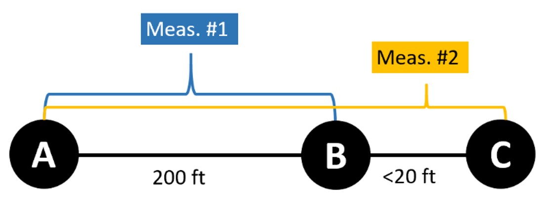
- If the distance between adjacent manholes is less than 20 feet (6 meters), then the acoustic measurement for the short segment should be coupled together with the next adjacent segment.
For example, if the distance between A and B is 200 feet, and the distance between B and C is less than 20 feet, then two measurements should be made.
• First measurement should be between manholes A and B for the 200 feet (61 meters) segment.
• Second measurement should be between manholes A and C for the combined 200 feet and <20 feet where b is skipped.
![]()
- Measurements can be conducted with or without the manhole cover fully removed, as illustrated in Figures 8 and 9.
- Once the acoustic measurement is completed, carefully remove the components from the manhole and deploy to the next segment. See Figure 5 for recommended “inchworm” deployment method.
 |
 |
| Figure 8. SL-RAT RX in Open/Measurement position – deployed with microphone centered and one foot below pane of manhole. Manhole cover removed for measurement. | Figure 9. SL-RAT TX in Open/Measurement position – deployment with manhole cover only partially removed for the measurement. |
STEP 3. Prepare RX (Receiver) Unit for Inspection
During an acoustic inspection for a pipe segment, the RX component receives the sound signal generated by the TX component. Based on the characteristics of the received signal, it assesses the condition of the pipe segment between the TX location and the RX location. After correctly deploying the RX, the steps for operating the RX are as follows:
| Ref # | User Display | Description |
|---|---|---|
| RX1 | RX Startup 1/2 |
From the RX Startup Screen, start the RX acoustic measurement operation by pressing the center button < START TEST >. Memory indicates how many acoustic measurements are stored in the device. The RX will require that records be uploaded to a computer when it reaches storage capacity at 500 measurements. |
| RX2 | Pipe Length Menu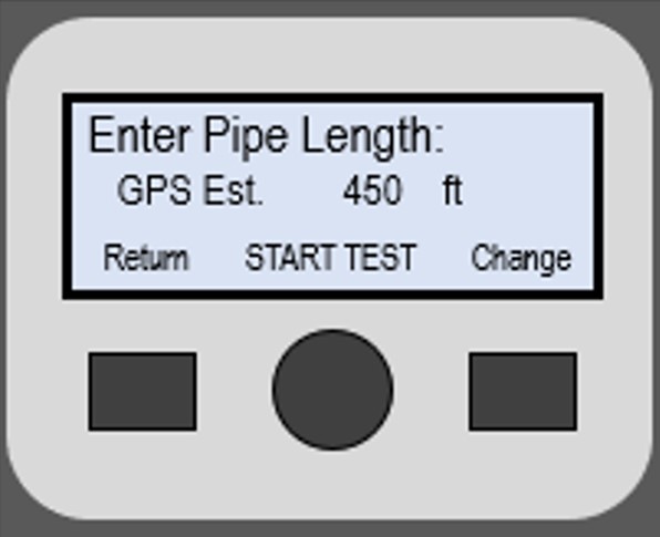 |
The next screen is the Pipe Length Menu. If the RX and TX are sufficiently close to each other, then the distance between the components is estimated based on GPS. The initial pipe length displayed on the screen will indicate if it is a GPS Est. (GPS Estimate) or the Default value (350ft.). Operator should verify or change this value as needed. It is important for the operator to record accurate pipe length distances to obtain accurate field assessment results.
|
| RX3 | RX Ready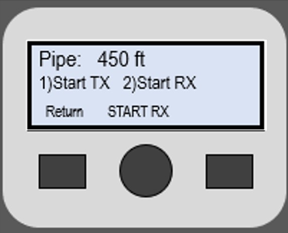 |
By verifying the pipe length, the RX is ready for the TX unit to begin test. Indicate to operator with TX to begin test – this is typically done via hand signal or walkie talkie. Remember: Start the TX before you start the RX. “Yell” before you “Listen” As soon as TX begins tone sequence (end of Step 4), press center button < START RX > |
STEP 4. Start Test on TX unit, then Start Test on RX unit
During an acoustic inspection for a pipe segment, the TX transmits a sequence of tones and this sequence is repeated up to 12 times over the duration of the measurement. The TX needs to be started prior to starting the RX. After correctly deploying the TX, the steps for operating the TX are as follows:
| Ref # | User Display | Description |
|---|---|---|
| TX1 | TX Startup 1/2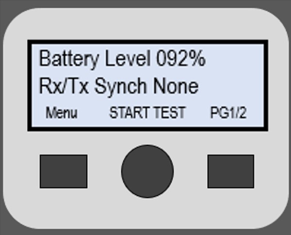 |
From the TX Startup Screen, start the TX acoustic measurement operation by pressing the center button < START TEST >.
RX/TX Synch Status indicates whether RX and TX need to synch. The devices automatically sync every time they are turned on. The TX will require synch if it reaches 200 unsynchronized records. Status can be as follows:
|
| TX2 | TX Start Test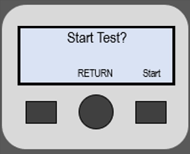 |
Once operator with RX signals that RX is ready, press right button < Start >. Operator with RX can press < Start RX > as soon as the TX begins emitting sound tones (Ref #RX3). |
STEP 5. Complete Test
The following screens will display as the test is being conducted. The TX will go through a series of tones 6 to 12 times. The test is complete once the RX provides an acoustic blockage assessment score (GOOD, FAIR, POOR, BLOCK):
During Testing: TX Display Screen
| Ref # | User Display | Description |
|---|---|---|
| TX3 | TX Real-Time Display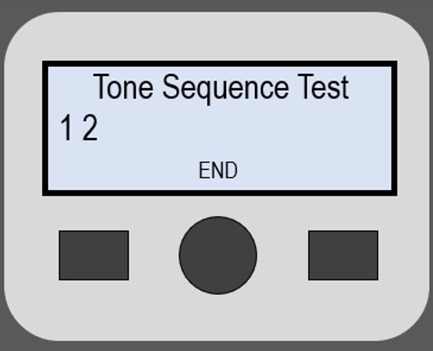 |
The TX Real-Time Display counts tone sequences transmitted. If TX and RX are able to communicate wirelessly, the TX should automatically stop producing tones once RX displays score (Ref #RX5). If it does not, operator can manually stop test by pressing and holding down center button < END >. At a maximum, the TX automatically ends the transmission after 12 tone sequences. While it is best to “end” the TX operation to maximize battery life once RX has reached an assessment, running through additional tone sequences does not impact the assessment score. |
| TX4 | TX Results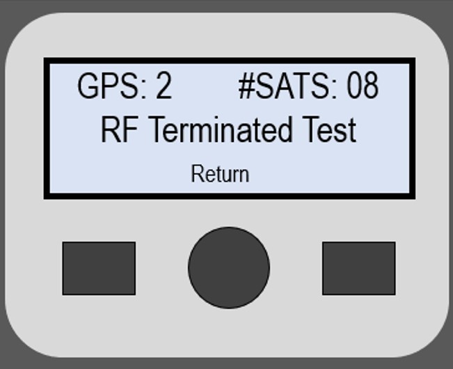 |
TX Results screen shows how the test was terminated, the GPS status, and number of Satellites
|
During Testing: RX Display Screen
| Ref # | User Display | Description |
|---|---|---|
| TX3 | RX Real Time Display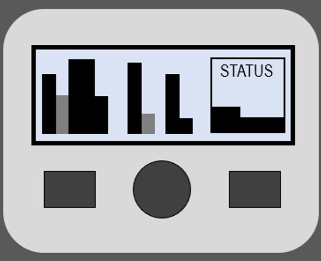 |
The RX Real-Time Display will provide graphics to indicate the RX is in test mode. The status bar on the right is incremented at one second intervals. After 16 seconds, a graphical display appears, which provides measurement status for individual components used in assessing the pipe status. |
STEP 6. View Test Result on RX
| Ref # | User Display | Description |
|---|---|---|
| RX5 | Pipe Segment Classification |
Once the testing is complete, the Pipe Segment Classification (see figure 9) is displayed first. The classification can be one of the following five possibilities:
|
| RX6 | Pipe Assessment Details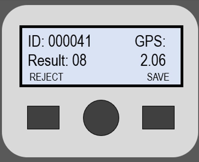 |
The Pipe Assessment Details shows the following:
|
To view collected acoustic data, download data then go to www.sl-dog.com and log in to access data in a secure, cloud-based web portal. Operators must create an account to access data. See Sewer Line Data OrGanizer (SL-DOG) Section Manual for more information.
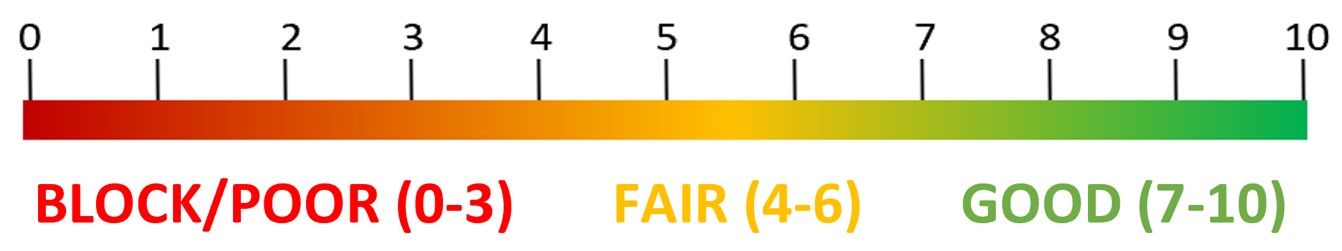
| Assessment | Typical Condition / Interpretation |
|---|---|
| 10 | No significant obstructions within the pipe. |
| 7 – 9 | Minor impediments within the pipe such as joint offsets, partial sags, protruding laterals, debris, minor grease, and/or minor root fibers. |
| 4 – 6 | Impediments within the pipe such as joint offsets, partial sags, protruding laterals, debris, grease, and/or root fibers. Single or multiple occurrences. |
| 1 – 3 | Significant impediments within the pipe such as multiple joint offsets, near full pipe sag, multiple protruding laterals, significant debris, significant grease, significant root fibers and/or root balls. Single or multiple occurrences. |
| 0 | Full pipe sag; single or multiple obstructions within the pipe reaching or nearly reaching the flow. |
Table 1. Description of typical conditions for each acoustic assessment score.
Post your comment on this topic.