
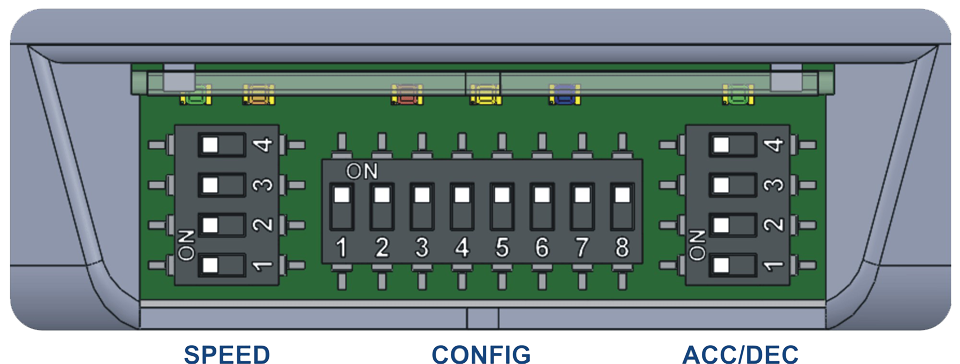
Each EZ-Qube Module module has three DIP Switches designated as SPEED, CONFIG and ACC/DEC
ON/OFF Switch Position
The DIP Switch and LED area on the EZ-Qube Module module utilizes a hinged clear plastic protective cover. Simply lift the cover from the bottom edge of the module to open the cover to gain access to the DIP Switches. Be sure to snap the cover back closed when done making and changes to the DIP Switch settings.

Motor Rotation Definition
The EZ-Qube Module uses a Clock-Wise (CW) and Counter Clock-Wise (CCW) motor rotation definition. The reference for this distinction is based upon viewing the MDR from the cable exit end of the roller.
