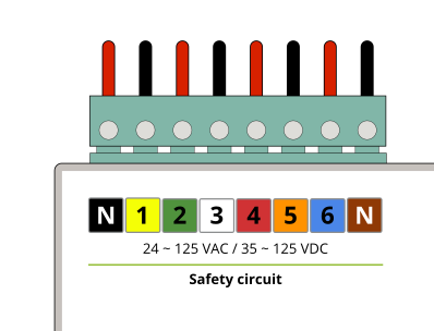
To monitor up to 6 satefy circuit signals, a specific terminal block is provided, as shown in the following image:
For connecting to the satefy circuits, it is essential to follow the instruction below to ensure proper operation of the system. The following diagram provides a simplified representation of the connection scheme for a single input:
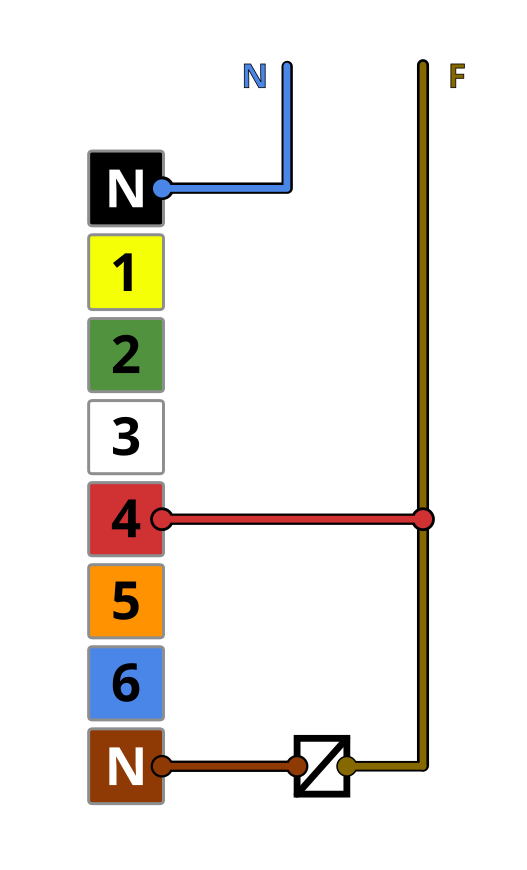
As it is shown in the previous image, the neutral wire for the safety circuits signals must pass through the MBB itself. This ensures the proper operation of the safety circuits
Hereinafter, an example with more signals connected:
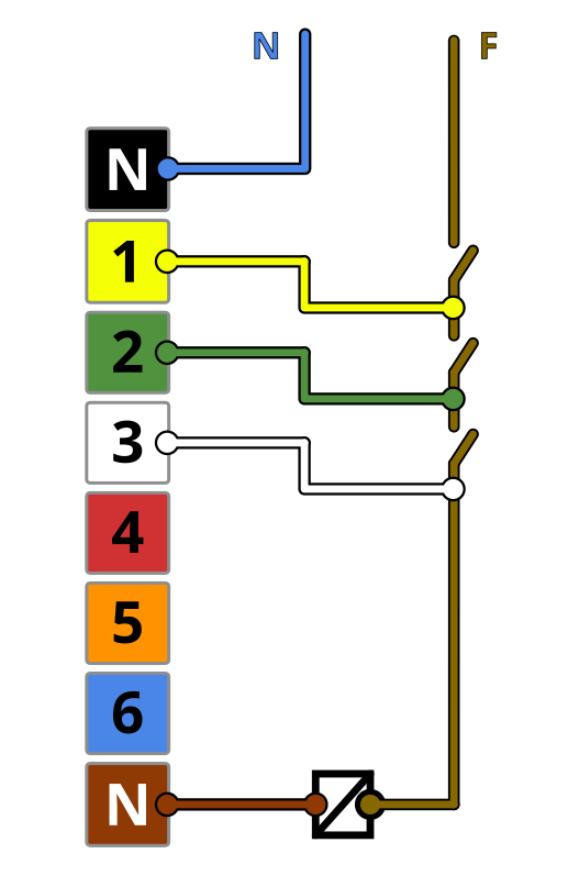
Although, up to 6 satefy circuits signals can be monitored, it is not compulsory to connect all of them, as it is shown in the previous example
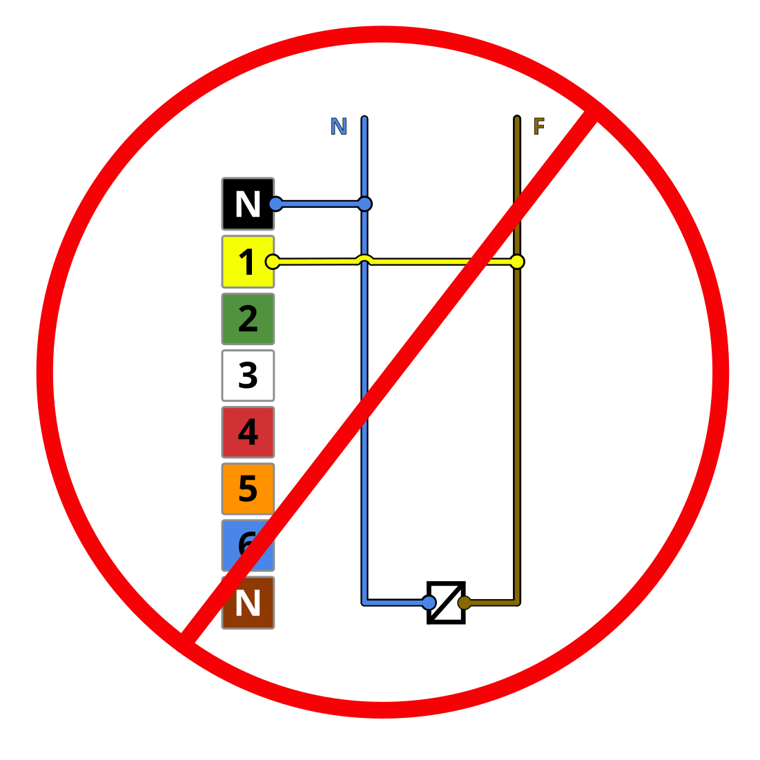
The following scheme shows an example of how safety circuit signals must NOT be connected: