English
Japanese
ConveyLinx-Ai Family Complete Guide
1.7
3.1
3.0
2.1
2.0
1.7
Table of Contents
ConveyLinx-Ai Family Complete Guide
1.7
ConveyLinx-Ai Family Complete Guide — 3.1
ConveyLinx-Ai Family Complete Guide — 3.0
ConveyLinx-Ai Family Complete Guide — 2.1
ConveyLinx-Ai Family Complete Guide — 2.0
ConveyLinx-Ai Family Complete Guide — 1.7
About This Manual
Glossary of Terms
Getting Started
Module Hardware
Identifying Module Components
Mounting Dimensions
Motor Ports
Sensor Ports
Electrical Connections for Sensor Port Aux I/O
Ethernet Ports
Power Connections
Power Supply Sizing
LED Status Indicators
Technical Specifications
Auto-Configuration
Device Connections to Modules
Examples that will generate errors
Motor Rotation Definition
Node Connections for a Subnet
Installing EasyRoll
ConveyLinx Ethernet Definition
Connecting Your PC to the Network
Auto-Configuration Procedure
Expected Results
What to do if things go wrong
Default Settings and Operation
Singulation Release Mode
Flex Zone Recognition
Jam Conditions
Arrival Jam
Sensor Jam
Automatic Module Replacement
Reset to Factory Default Settings
EasyRoll Software
Main Screen
Node Navigation
Node Identification
ZPA Upstream/Downstream Zone Settings
Release Mode
Singulation Release
Train Release
GAP Train Release
T-Zone Settings
ZPA Error and Information
Accumulate Control from Main Screen
Settings Checkboxes
Disable Reset Delays
Disable Sensor Jam Auto Clear
Disable Arrival Timeout
Disable Manual Operation
Motor Settings
Motor Type
Brake Method
Speed
Rotation Direction
Acceleration/Deceleration
Motor Jog and Error Indicators
Diagnostic Window
Advanced Dialog
Look Ahead and Timing Tab
Look Ahead Slowdown Feature
Jam & Auto Clear Timers
Run After Time/Distance
Induct Forward Time/Distance
Sensor Debounce
Upgrade Tab
Connections Tab
Network Services Tab
Discover & IP Address Set
Backup & Restore
Special Services Tab
Flex Zone Tab
Sensors Tab
Extensions Tab
Pin 2 Usage Tab
Most Downstream Zone
Most Upstream Zone
Accumulate Intermediate Zone
Lane Full Interface
Most Upstream Zone Handshake Interlock
Most Downstream Zone Handshake Interlock
Inverting the Pin 2 Signals
IOX Interface Module
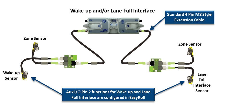
Wake up and/or Lane Full Interface
Wake up/Lane Full with Wired Terminals
Wake up/Lane Full with Discrete Signals
Wake up/Product on Zone Handshake Interlock
Downstream/Product on Zone Handshake Interlock
Pin 2 Output on Aux I/O M8
Pin 2 Output on Wired Terminals
Download as PDF
Wake up and/or Lane Full Interface
IOX Interface Module
Wake up/Lane Full with Wired Terminals
IOX Interface Module
Wake up/Lane Full with Wired Terminals