
Displacement
Distorts the currently selected background based on color or tonal data.

- Type: Select the type of displacement to be used, from this menu.
- From background: Uses the image beneath the selected layer as the source for generating the displacement.
- From map: Uses an external image of your choice as the source for generating the displacement.
- Select file: When Onto Map is selected, this property will appear, where you can choose an image to be used as the source of the displacement. Click the file icon at the right to open a file explorer window and choose an image.
- Channel: Choose the channel of the source image that will be used to generate the distortion.
- Luminance: Distorts the target layer based on the luminance channel of the selected image, which values of 0 in the luminance channel having no effect, and values of 255 having full effect.
- Red: Distorts the target layer based on the red channel of the selected image, which values of 0 in the red channel having no effect, and values of 255 having full effect.
- Green: Distorts the target layer based on the green channel of the selected image, which values of 0 in the green channel having no effect, and values of 255 having full effect.
- Blue: Distorts the target layer based on the blue channel of the selected image, which values of 0 in the blue channel having no effect, and values of 255 having full effect.
- Alpha: Distorts the target layer based on the alpha channel of the selected image, which values of 0 in the alpha channel having no effect, and values of 255 having full effect.
- Contrast: Modifies the contrast of the source image, to manipulate the results of the distortion.
- Smooth detail: Blurs the source image, to reduce the details used in the distortion.
- View map: Shows the map being used to generate the displacement.
- Shift X: Adjust the amount of distortion applied on the X (horizontal) axis.
- Shift Y: Adjust the amount of distortion applied on the Y (vertical) axis.
- Edges: Choose how the effect is handled around the edges of the image.
- No Repeat: When the edge of the image are distorted out of place, the space at the edges remains empty.
- Tile: When the edge of the image are distorted out of place, the space at the edges is filled with a repeated copy of the image.
- Mirror: When the edge of the image are distorted out of place, the space at the edges is filled with a mirrored copy of the image.
- Blend highlights: Increasing this value makes the highlights of the source image visible on the target image.
- Blend shadows: Increasing this value makes the shadows of the source image visible on the target image.
Fractal Distortion
Fractal distortion creates fractal noise patterns, then uses displacement to apply the noise to your image, thereby warping and distorting it.
Basic Controls
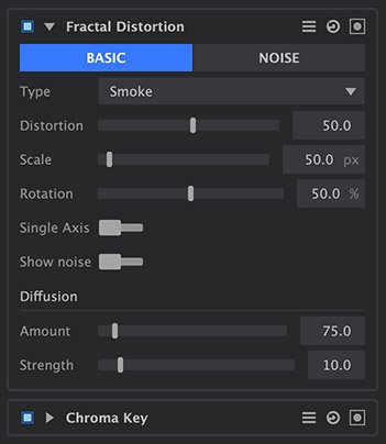
- Type: Each type uses a different fractal, to give a different appearance to the pattern.
- Heat: Simulates the distortion of looking through a heat haze.
- Smoke: Soft, billowing shapes like the texture of smoke.
- Energy: A pattern of thin, energetic strings.
- Fluid: Replicates a pattern similar to the caustics created by looking through a volume of water.
- Distortion: Adjusts the intensity of the distortion applied to the layer.
- Scale: Sets the scale of the distortion
- Rotation: Sets the angle in which the distortion is applied.
- Single Axis: Enabling this option applies the distortion in a single direction. The specific angle used can be set with the Distortion Rotation setting above.
- Show Noise: By default, the noise generated by this effect is automatically converted to distortion, and applied to the image. Enable this option to view the noise directly.
Diffusion
- Amount: Adjusts the prevalence of areas which are blurred, or diffused, by the distortion.
- Strength: Sets the strength of the blur in the areas affected by diffusion.
Noise Controls
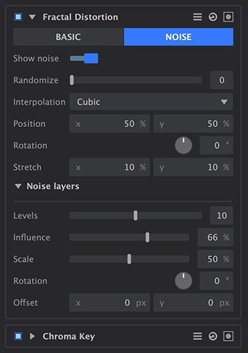
- Show noise: The final result of this effect is created by converting the noise it generates into distortion, and applying it to the image. Enable this option to view the noise directly.
- Randomize: Acts as a randomizer for the shape of the noise. Each seed value sets a unique starting shape for the procedurally generated noise.
- Interpolation: Choose the method used to build the texture from the fractal geometry.
- Block: Creates a square, pixelated appearance.
- Linear: Applies more gradual transitions from one block to the next.
- Cubic: More dramatic gradients completely obscure the block pattern to create organic shapes.
- Position: Moves the origin point of the fractal pattern on the X (horizontal) and Y (vertical) axes. X values run from 0 on the left to 100 on the right. Y values run from 0 at the top to 100 at the bottom.
- Rotation: Rotates the pattern around the origin point.
- Stretch: Alters the width and height of the pattern independently, allowing you to stretch it into more linear patterns.
Noise Layers
The noise layer settings affect the additional iterations of the fractal which are used to break up the primary fractal and create the finer details.
- Levels: Sets the number of iterations of noise which will be combined to create the noise map.
- Influence: Adjusts the balance of the original fractal and the additional iterations. Values below 50% favor the original, and values above 50% favor the iterations.
- Scale: Adjusts the size of the iterations, without altering the original.
- Rotation: Rotates the iterations, without rotating the original.
- Offset: Adjusts the position of the iterations on the X (horizontal) and Y (vertical) axes, without altering the original. X values run from 0 on the left to 100 on the right. Y values run from 0 at the top to 100 at the bottom.
Quad Warp
Use quad warp when you need to reposition the corners of a layer individually, to alter its perspective or to alter the scale of its contents non-uniformly. The effect provides controls for each individual corner of the layer.
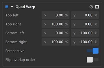
- Top left: Defines the X (horizontal) and Y (vertical) positions of the top left corner of the layer. X values run from 0 on the left to 100 on the right. Y values run from 0 at the top to 100 at the bottom.
- Top right: Defines the X (horizontal) and Y (vertical) positions of the top right corner of the layer. X values run from 0 on the left to 100 on the right. Y values run from 0 at the top to 100 at the bottom.
- Bottom left: Defines the X (horizontal) and Y (vertical) positions of the bottom left corner of the layer. X values run from 0 on the left to 100 on the right. Y values run from 0 at the top to 100 at the bottom.
- Bottom right: Defines the X (horizontal) and Y (vertical) positions of the bottom right corner of the layer. X values run from 0 on the left to 100 on the right. Y values run from 0 at the top to 100 at the bottom.
Viewer controls
The quad warp effect can also be controlled directly on the viewer, which in many cases is more intuitive and effective.
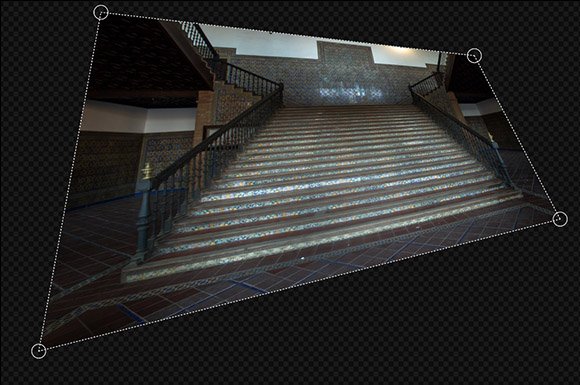
- Corner handles: On the viewer, when the quad warp effect is selected, circular control points will appear at each corner of the layer, connected by dotted lines. Dragging the corner handles to reposition them directly controls the warp effect.
Need more help with this?
Don’t hesitate to contact us here.