
Purpose
You should use this feature if you want to:
- design fiber networks that are to be rolled out in different phases;
- obtain a Bill of Material file that, next to the inventory and the costs of the complete network, contains detailed information about equipment and costs of the partial networks in the individual roll-out phases.
Mechanism
At the start of a network design with a phased roll-out schedule, you need to provide information about the geographical sub-areas and the roll-out phases assigned to them. Next to that, you have to indicate in the Rules & Material file how you want to handle transitions between the roll-out phases.
After calculation of the network, you obtain a design that is laid out in accordance with the roll-out phases you indicated. Based on the dig only once principle, the design includes all the equipment necessary for the deployment of the each phase, but also to start the deployment of the next phase without carrying out ground works in an area that was rolled out previously.
The Bill of Material file offers an overview of the global network and its costs, but additionally it provides separate sheets per roll-out phase with a detailed breakdown of the costs,
Required Input
The information about the sub-areas and their respective roll-out phases is provided through a GIS input file IN_RollOutPhases.shp, located in the \input\CalculationInput folder of your Area View project. This file contains features of geometry type POLYGON and you can load it when initialising or updating a workspace.
To indicate the roll-out phase in which each sub-area is scheduled, the input file should include the attribute PHASE with a numeric value for each polygon (sub-area). This value can be a simple number indicating a sequence or it can be a year. The lowest value is considered to be the first phase of the roll-out schedule.
As to the shape, the lay-out and the number of polygons that the input file can contain, there are no strict limitations. You can use adjacent polygons that are neatly separated from one another or you can use polygons that partly coincide. Comsof Fiber Designer is able to assess the unique roll-out phase to which each demand point belongs.
Rules and Material File Setting
On the Common page of the Rules & Material file, you can indicate if extension equipment should be placed between roll-out phases. You can also establish the type of the equipment.
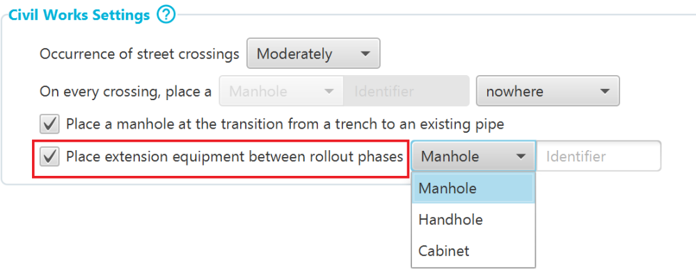
If you select this option, the network design for a given roll-out phase incorporates a piece of the selected equipment at spots where the network infrastructure of that phase stops. This is to provide an efficient starting point for the deployment of a subsequent roll-out phase. If the deployment of the subsequent phase can be started from acces equipement that is already present, no extra extension equipment needs to be placed.
Output
- QGiS visual output and GIS output files
The major visual impact on the presentation of the calculated network is that in the Design View, the polygons representing the roll-out phases are also displayed. This allows you to carry out a quick first visual inspection.
As to the output files, all the different types of equipment receive the PHASE attribute with the appropriate value from the sub-area polygons in theIN_RollOutPhasesinput file. Using the QGIS styling features and the value of the PHASE attribute, you can make the different roll-out phases also clearly visible in the Layers pane of the project.
Additionally, each piece of equipment receives the DEPLOYMENT attribute, with the valueTorF. The former value indicates that a piece of infrastructure is required for the full connection/activation of demand points during the scheduled roll-out phase (or subsequent one). The latter value is used for equipment that can be placed at a later stage because it is related to demand points that are not yet scheduled for full connection. Refer also to the topic on the Connection feature.
In the GIS output files of the different network layers, each piece of the network infrastructure takes over the PHASE attribute and value from the IN_RollOutPhases input file according with the roll-out phase for which it is scheduled.
- Bill of Material file
In case of a design with phased roll-out, the BOM, in addition to the global overview of the entire network and its cost, contains detailed information about the network infrastructure in the different roll-out phases.
It contains a separate tab sheet for each roll-out phase listing the detailed costs for every layer of the network.
But also on the tab sheets BOM per DP and BOM per CO, the costs for both deployment and activation are broken down per roll-out phase.
Interaction with CONNECTION attribute
The CONNECTION attribute can be set on Demand Points to indicate up to what level the network infrastructure is to be placed, depending whether or not the demand point is scheduled for full connection/activation right away. In combination with the phased roll-out feature, the values for the CONNECTION attribute will determine values for the DEPLOYMENT attribute. If for demand points in a certain sub-area the value for the CONNECTION attribute is set to any other value than FULL, the infractructure needed to connect these demand points will have the DEPLOYMENT set to F.